Lights Out Arcade Box
Over the past year I’ve been working on my first big hardware project. It started as an experiment in powering and controlling led displays. I love the blinky lights and wanted something big that would catch the eye.
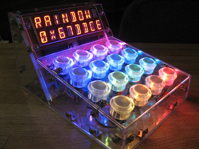
The end result is a tabletop sized arcade for a 4x4 lights out game similar in gameplay to the Mini Lights out Game by Tiger Electronics.
Checkout a video demo of the gameplay here on vimeo.
This project took me a long while to complete due to lack of free time. I began when my son turned one year old and finished not long before he turned two. The effort paid off though and I’m happy with how it turned out.
Parts
I took the lego approach while putting this together. Pick powerful components and wire them up. Here is a list of every part used and what I paid for it.
| Price | Quantity | Item |
|---|---|---|
| $02.50 | 5/64 inch Balldriver | |
| $02.85 | ATMEGA328P | |
| $02.95 | MCP23017 - i2c 16 input/output port expander | |
| $04.50 | 2 | 4xAA Battery Holder |
| $05.00 | Various resistors and capacitors mostly 0.1µF | |
| $05.95 | Waterproof Metal On/Off Switch with Green LED Ring | |
| $06.46 | 6-32 x 3/8 inch Button Socket Cap Head Screw | |
| $06.95 | Premium Female/Female Jumper Wires - 40 x 6” | |
| $06.99 | Wire-Wrapping Tool | |
| $10.20 | Right Angle Mounting Bracket | |
| $14.95 | FTDI Friend + extras - v1.0 | |
| $14.95 | Pololu Step-Down Voltage Regulator D15V35F5S3 | |
| $21.90 | 10x30ft of kynar wire | |
| $26.40 | 16 | 0.8 inch Alphanumeric Displays |
| $32.96 | Clear Lasercut Acrylic from Ponoko | |
| $34.18 | Wire wrap sockets Part Numbers: HWS3089, HWS15765, HWS1462 | |
| $39.95 | 12mm Diffused Thin Digital RGB LED Pixels (Strand of 25) - WS2801 | |
| $42.56 | 16 | Arcade Button - 30mm Translucent Clear |
| Free Sample | 2 | MAX6954 4-Wire Interfaced, 2.7V to 5.5V LED Display Driver with I/O Expander and Key Scan |
Total: $282.20
Most of these parts are overkill and I’m sure this project could be accomplished cheaper and more efficiently. Some parts don’t seem to be available anymore. Even so, it has a lot of character and thats what I was going for.
Board Layout
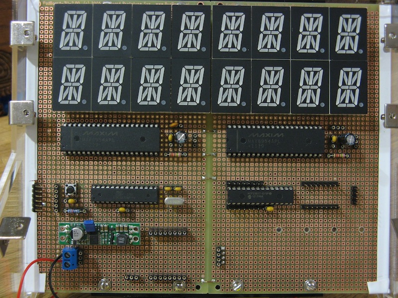
Here you can see the layout of the components. I couldn’t find a through hole protoboard that was large enough to accommodate all of the alphanumeric digits so I fastened two together and used some legos attached to with screws for reinforcement.
The 17-segment displays

Below the alphanumeric digits are the MAX6954 drivers. There is one driver per row. Next to each driver are decoupling capacitors and a resistor for limiting the current to each segment. The diagram to the right details the required connections. These are pretty beefy chips. They do a lot and have a built in font map that correspond to ASCII character codes. Getting characters to display is as simple as sending a string over the SPI connection.
The MAX6954 datasheet claims they are chainable but I was getting garbage on the second display when wiring the SPI bus in a chain. It worked much better when each chip had it’s own chip select line and I sent commands to both or one at a time.
For extra fun I also wanted to see some lowercase characters so I created my own font map and displayed it by turning individual segments on and off.

Connecting each chip to 8 digits was the hardest part of this build. Wire wrapping that many connections took about 6hrs total. Below is the connection scheme in a table from the datasheet. The chip uses charlie-plexing to control that many segments. Most of the MAX6954 pins are connected to a single segment on each digit. Pins 0-7 are connected to two segments.
Before I began I drew the connections with pencil and paper. I picked different colored wire for each row and tested that each point was connected properly using a multimeter. Thankfully I didn’t have to repair any connections after finishing.
I chose to wire wrap the whole thing because I wasn’t 100% sure how to connect everything to start with. Unfortunately I’m lacking a proper circuit schematic. Learning how to use Eagle or gEDA is still on my todo list. I was able to get away with this because the connections outside of the digits are relatively simple and I could rewire anything quickly if needed.
Buttons and RGB LEDs
The remaining components include a MCP23017 port expander, 16 buttons and a RGB LED strand with 16 pixels for the button grid. I was a bit lazy and decided to use the MCP23017 to read the state of each individual button rather than create a button array wired to one of the analog inputs of the ATMEGA328P. Each button is connected to one pin of the MCP23017 and ground. In the code it’s very simple to get the state of each button as a 16 bit unsigned integer.
The RGB LED strip is dead simple to use with the tutorial and provided library. The strip isn’t arranged in the same order as I was representing the game board in the code. To deal with that I store the position of each light on the strip in the correct location in an array. I then use bit masking and shifting to determine if a single bit in the 16-bit unsigned integer is a 1 and if so set the light to on. Here is the loop I use to turn the lights on and off for a given board:
1 2 3 4 5 6 7 8 | |
Color Chooser
In addition to the lights out game I wrote up a quick color chooser. With it you can increase or decrease the amount of red green and blue and see the hex color code. There is also a button to generate a random color and another to start a rainbow color rotation if you are in need of a dopamine squirt. Once you have a color you like you can save it in the EEPROM and have it used in your next lights out game. Checkout the demo for an example of how it works.
Solving a Game
One feature I really wanted was to be able to display the solution to a given board. A post on Merlin’s magic square at cut-the-knot.org pointed me to an article in Mathematics Magazine, Vol. 74 An Easy Solution to Mini Lights Out(pp. 57-59) Jennie Missigman and Richard Weida The gist of this article points out a few unique properties of 4x4 lights out games that are periodic (wrap around).
- Every game is solvable
- The order of buttons pressed does not matter
- The solution to any game can be found by multiplying a matrix by a column vector that represents the status of the board. 1’s represent lights turned on, 0’s off.
Armed with this knowledge I was able to add random levels (which are all solvable), a solution function, and the total number of moves required to win.
At first I planned to generate all levels randomly but it turns out that random levels are extremely hard to win. They have no patterns that aid in solving. To address that I wanted to include the original levels that were part of the Mini Lights out Game. You can find them at Mini Lights Out Levels and Solutions on Jaap’s Puzzle Page.
Code
The Lights Out Arduino Sketch is pretty well organized. I’ve also written a library for controlling the MAX6954’s. which keeps the lights out code simpler.
The sketch is organized into separate files. When compiled in the Arduino IDE the files are concatenated and then compiled as a single source file. The lights out and color chooser functions are broken out into their own classes. All strings and levels are stored in program memory.
Each level, and the state of the board, is represented by a 16-bit unsigned integer. Literally 16 1’s or 0’s. This makes it take up very little space. To compute a solution for a given board a matrix vector multiplication needs to be performed. The 16x16 matrix is composed of only 1’s and 0’s so to save space I store it as an array of 16 bit integers.
1 2 3 4 5 6 7 8 9 10 11 12 13 14 15 16 17 18 19 20 21 22 23 24 25 26 27 28 29 30 31 32 33 34 35 36 37 38 | |
Packing the matrix value like this adds a bit of code to the matrix vector multiply. It’s still quite readable though. If you are unfamiliar with bitmath checkout The Arduino Playground Bit Math Tutorial and Bit Twiddling Hacks
1 2 3 4 5 6 7 8 9 10 11 12 13 14 15 | |
As a side note, it’s pretty easy to convert number bases in your editor if you
can filter text through an external program. This is trivial in vim and is
possible with other editors like TextMate. In vim, I filter the following text
through bc “An arbitrary precision calculator language” available on almost
any Linux distribution and MacOSX. The first two lines tell bc to output base 16
and take base 2 as input (they should be set in that order).
1 2 3 4 5 6 7 8 9 10 11 12 13 14 15 16 17 | |
The result, instant base 16 without leaving the editor!
1 2 3 4 5 6 7 8 9 10 11 12 13 14 15 16 | |
Enclosure
This is the first time I’ve tried to design any kind of enclosure. I started by picking a material on Ponoko for laser-cutting. Once I knew what I was working with I began creating panels in Sketchup and tried to make a box that would fit the circuit board and accommodate 16 buttons.
I was aware of the tab in slot method for designing an enclosure but by this time I had a lot of project fatigue and decided to put put it all together with angle brackets. It was easy to create the angle brackets in sketchup so I could have the screw holes precut. One thing I should have done is round the corners of each panel. The right angles are sharp! I ended up sanding each corner until they were rounded by hand.
After finishing the design I flattened each panel and arranged it to fit in the Ponoko P3 sized order using the SVG Sketchup plugin. You can download the sketchup file and have a look if you wish.
Improvements
There are definitely some improvements I can still make. If I were to build this whole thing again from scratch I would make these changes:
- Design a circuit board instead of wire wrapping
- Tab-in-slot method enclosure
- Better arcade buttons with a more clicky feel
- Better way to fasten the RGB LEDs to the buttons, maybe add additional holes in the enclosure.
- A red contrast filter for the 17 segment characters, they are way too bright.
- Better button debouncing code
Thanks for reading! You can find more pictures at full resolution in my dropbox.


